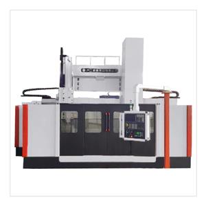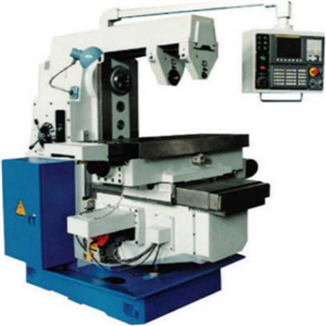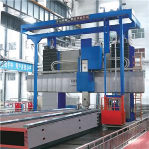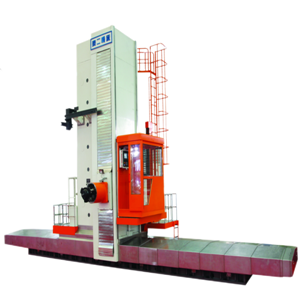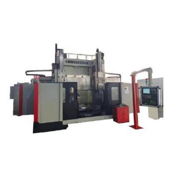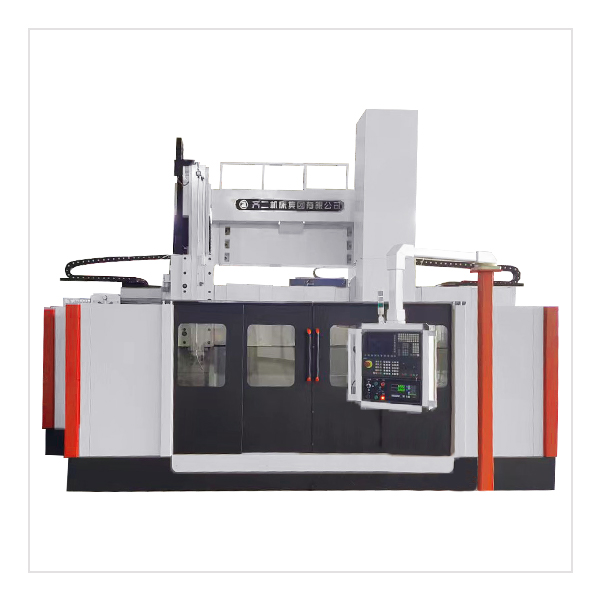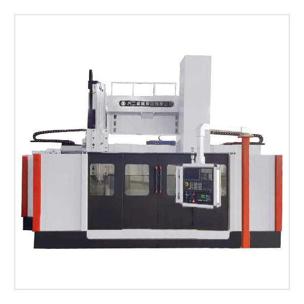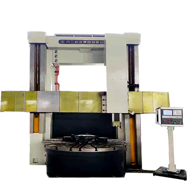
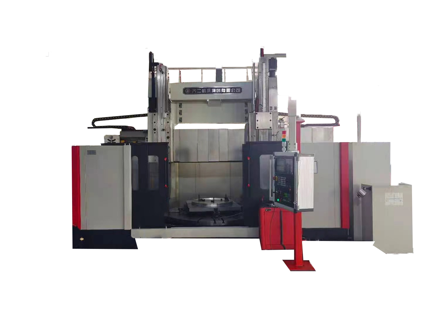
Ordinary Double-column Vertical Lathe
Brand QIER WAJI CNC MACHINE
Product origin CHINA LIAONING
Delivery time 3 months
Supply capacity 2-5 units per month
1.Ordinary double-column vertical lathe is suitable for machining in various industries, and can be used for rough and fine turning of inner and outer cylindrical surfaces, conical surfaces, end faces and grooving.
2. The worktable of the Ordinary double-column vertical lathe adopts dynamic pressure guide rail, and the radial direction of the main shaft adopts NN30 double-row cylindrical roller bearings, so the worktable has a large bearing capacity and high rotation accuracy.
3. The machine tool electrical of Ordinary double-column vertical lathe adopts PLC control and is equipped with digital display device, which has higher reliability.
4.Ordinary double-column vertical lathe has beautiful appearance, good pleasantness and convenient operation.
5. Provide side tool holder and turning taper accessories according to special requirements.
Introduction of Ordinary double-column vertical lathe:
Two-column vertical lathes are the main equipment for roughing and finishing.Its traditional structure makes the whole machine more compact and its traditionally mechanical transmission system makes it easier to operate, high versatility and convenient for maintenance. The machine can be installed with optional devices,such as DRO device, side railhead and others.

Double Column vertical Lathe D series(2.5-4 meters):
Double Column vertical Lathe D series(2.5-4 meters) | ||||
Product Model | C(X)5225D×H/W | C(X)5231D×H/W | C(X)5235D×H/W | C(X)5240D×H/W |
Max.machining diameter(mm) | φ2500 | φ3150 | φ3500 | φ4000 |
Max.height of workpiece (mm H×100) | H=16/20/25 | H=16/20/25/31 | H=16/20/25/31 | H=16/20/25/31/36 |
Max.weight of workpiece(t) | W=10/20 | W=10/20/32 | W=10/20/32 | W=10/20/32 |
Diameter of workbench(mm) | φ2250 | φ2250/φ2830 | φ2250/φ2830/φ3150 | φ2830/φ3150/φ3600 |
Workbench rotate speed/steps | 16 | 16/18 | 16/18 | 16/18 |
Workbench rotation speed limits(r/min) | 2-63 | 2-63/1-50 | 2-63/1-50 | 2-63/1-50 |
Max.torque of workbench(KN.m) | 63 | 63/80 | 63/80 | 63/80 |
Travel of crossbeam(mm) | 1250/1650/2150 | 1250/1650/2150/2800 | 1250/1650/2150/2800 | 1250/1650/2150/2800/3250 |
Crossbeam lifting speed(mm/min) | 350 | 350 | 350 | 350 |
Crossbeam lifting motor power(KW) | 7.5 | 7.5 | 7.5 | 11 |
Horizontal stroke of left/right vertical tool holder(mm) | (-15~1400) | (-15~1750) | (-15~1950) | (-15~2150) |
Vertical stroke of left/right vertical tool holder(mm) | 1000/1250/1400/1600 | 1000/1250/1400/1600 | 1000/1250/1400/1600 | 1000/1250/1400/1600 |
Feed steps of tool holder | 18 | 18 | 18 | 18 |
Feed limits of tool holder(r/min) | 0.2-145 | 0.2-145 | 0.2-145 | 0.2-145 |
Rapid traverse speed of tool holder(mm/min) | 1550 | 1550 | 1550 | 1550 |
Swivelling angle of tool holder | ±30° | ±30° | ±30° | ±30° |
Section of tool shank(mm) | 40X50 | 40X50 | 40X50 | 40X50 |
Max.cutting force of right vertical tool holder(KN) | 35 | 35 | 35 | 35 |
Max.cutting force of left vertical tool holder(KN) | 28 | 28 | 28 | 28 |
Section of left/right ram(mm) | 255X200 | 255X200 | 255X200 | 255X200 |
Ram form | "T" ram | "T" ram | "T" ram | "T" ram |
Main motor power(KW) | 55 | 55 | 55 | 55 |
Weight of lathe(appprox.)t | 36/38/42 | 38/40/44/47 | 40/42/45/48 | 45/48/53/57 |
Vertical stroke of right tool holders' pentagonal turret(mm) | (1000/1250/1400) | (1000/1250/1400) | (1000/1250/1400) | (1000/1250/1400) |
Max.machining diameter of side tool holder(mm) | Options(φ2300) | |||
Horizontal stroke of side tool holder(mm) | Options(700) | |||
Vertical stroke of side tool holder(mm) | Options(1200) | |||
cutting force of side tool holder(KN) | Options(2800) | |||
Workbench guideway forms | slide guide(W=10) | slide guide(W=10) | slide guide(W=10) | slide guide(W=10) |
DRO control | Option | Option | Option | Option |
Protective device | Option | Option | Option | Option |
Coolant system | Option | Option | Option | Option |
Servo stepless feeding | Option | Option | Option | Option |
PLC | Option | Option | Option | Option |
Ordinary double column D series(5-6.3m):
Ordinary double column D series(5-6.3m) | |||
Product number | C(X)5250D×H/W | C5250×H/W | C5263×H/W |
Maximum cutting diameter mm | φ5000 | φ5000 | φ6300 |
Maximum turning height mm (H×100) | H=20/25/31/36 | H=31/36/40 | H=31/36/40 |
Maximum workpiece weight t | W=(32/40) | W=50 | W=50/80 |
Table diameter mm | φ3600/φ4000 | φ4500 | φ5000/φ5700(W=80) |
Table speed range r/min | 1-50 | 0.5-50 | 0.5-50/0.32-32 |
Table speed series | 18 grades/two grades stepless | stepless two | stepless two |
Maximum torque of worktable KN.m | 80 | 100 | 100/150(W=80) |
Beam travel mm | 1650/2150/2800/3250 | 2650/3100/3500 | 2650/3100/3500(W=80) |
Beam lifting speed mm/min | 350 | 310 | 310/300(W=80) |
Beam lift motor power KW | 18.5 | 18.5 | 18.5/30(W=80) |
Horizontal stroke of left and right tool rests mm | (-15~2765) | (-20~2765) | (-20~3415) |
Left and right tool rest vertical stroke mm | 1250/1400/1600 | 1600 | 1600/2000(W=80) |
Left and right tool post feed range r/min | 0.2-145 | 1-500 | 1-500 |
Left and right tool post feed stages | 18 | stepless | Stepless |
Rapid traverse speed of left and right tool rests mm/min | 1550 | 3000 | 3000 |
Left and right tool post transfer angle range | ±30° | (-15~30°) | (-15~30°) |
Cross-sectional dimension of left and right tool rest rams mm | 255X200 | 240X240 | 240X240/280X280(W=80) |
Cross-section dimension of turning tool holder mm | 40X50 | 50X50 | 50X50 |
Maximum cutting force of left vertical tool holder KN | 28 | 35 | 35/50(W=80) |
The maximum cutting force of the right vertical turret KN | 35 | 50 | 50/63(W=80) |
Left and right tool rest ram structure | "T" shaped ram | rectangular ram | rectangular ram |
Main motor power KW | 55 | 75 | 75/90(W=80) |
Machine weight (approx.) t | 68 | 100 | 120/160(W=80) |
Workbench bearing guide rail structure | Hydrostatic guide | Hydrostatic guide | Hydrostatic guide |
Digital display device | Options | Options | Options |
Simple protective device | Options | Options | Options |
cooling device | Options | Options | Options |
Linear axis servo motor drive feed | Options | configure | configure |
PLC control | Options | configure | configure |
Other models of Ordinary double-column vertical lathe:
Ordinary double-column vertical lathe C(X)5226*16/10,Ordinary double-column vertical lathe C(X)5225,Ordinary double-column vertical lathe C(X)5231,Ordinary double-column vertical lathe C(X)5235,Ordinary double-column vertical lathe C5240,Ordinary double-column vertical lathe C5250,Ordinary double-column vertical lathe C5263,Ordinary double-column vertical lathe C5280,Ordinary double-column vertical lathe C52100
Application scope of Ordinary double-column vertical lathe:
Automobile and motorcycle field, electrical equipment field, construction machinery field, military industry field, transportation, aerospace, education field, electronic product field
Ordinary double-column vertical lathe operation process should pay attention to:
1. The rough surface of the workpiece is not allowed to be placed directly on the work surface, and should be supported by a pad iron or a screw top; it is strictly forbidden to use the work surface for other operations such as calibrating the workpiece by hammering, welding the workpiece, etc.
2. When aligning the workpiece, you can only jog the worktable to rotate at a low speed for alignment, and high-speed alignment is not allowed.
3. When starting and stopping the workbench, the handle of the workbench can only be moved by hand, and pedals are strictly prohibited.
4. When the worktable is rotating, it is not allowed to do the lifting of the beam and the rapid movement of the tool rest.
5. When moving the beam, the clamping device must be released first, and it should be clamped immediately after the movement. After the beam is lowered each time, it should be raised a little to eliminate the clearance between the lead screw and the nut.
6. When performing interrupted cutting, appropriately reduce the amount of feed and the speed of the worktable.
7. The operating lever must be pushed to the specified position when shifting. If the gears are not meshed properly, they should be adjusted by inching after work, and forced operation is not allowed.
